Serial Secrets for PocketPC's
I've been battling with manufacturer's dumb decisions about
accessory
cables included with well designed tiny compact devices for years.
When I got my first digital camera, the tiny Kodak DC20, it's serial
cable alone weighed more and required more storage space than the
camera
itself. In some cases, cables for delicate devices look like they
came out of the prop department for a 30's Frakenstein movie, big
enough
to power all of New York City. It's rare to encounter any current
device manufacturer who understands the need to minimize and streamline
all components of their systems to make them as portable as possible.
The Jornada's serial cable is not the worst, but far larger and more
expensive than it has to be. My approach to dealing with multiple
connection
issues is to set up all of the computers that I will be connecting with
with easily available and inexpensive standard cables and then minimize
a single adapter for the device that will allow it to connect with a
minimum
"carry weight"
This approach also allows future connecting to unexpected devices as
simple and easy as possible, with either standard cables that I have
with
me or that can be found at almost any electronic store.
USB Mini Connector and
Power
PDA2k Pinouts (Serial,
USB, Power)
The following are my oberseravtions and no
warranty is made as to it's accuracy... use the following information
at
your own risk. The following may be
relevant
for other iMate devices, but I have no evidence of any kind that they
use
the same connectors and/or pin sequences.
 The
PDA2k uses a connector that is similar to the current IPaqs, but is
wired
very differently... DO NOT USE IPAQ
CABLES
AND CONNECTORS with the iMate Devices
as they use totally different pin assignments incuding power input
differences
which may destroy your device if you do!
The
PDA2k uses a connector that is similar to the current IPaqs, but is
wired
very differently... DO NOT USE IPAQ
CABLES
AND CONNECTORS with the iMate Devices
as they use totally different pin assignments incuding power input
differences
which may destroy your device if you do!
If you intend to make custom cables, I
strongly
recommend using premanufactured cables and modifying them to meet
special
needs as the soldering demands connecting directly to the connector
solder
lugs are high along with the dangers of leaving accidental connections
within the connector shell that may destroy your device. I
recommend
the "PDA2k
Serial Sync" cable from Expansys for most needs as it incorporates
a standard mini coaxial power jack into the shell that allows using
common
PPC power supplies such as those for the Ipaq series.
The image shows a "minimal" serial cable
created
from the PDA2k
"Power Adapter" available at Expansys for $14. It uses the "RJ
Serial" connector system that I have been using for almost two
decades
that continues to serve me well, especially in mobile environments. My
"carry kit" contains a variety of connectors that run from DB9 and DB25
connectors, to nulmodem modules, Mac serial connectors, multiple PDA
adapters
and even a few camera serial connectors. The Black Cable is the
Expansys
"Serial Sync" cable, shown to underscore that custom cables can achieve
a significant reduction in size, weight and flexibility.
The following pin numbers are derived by
looking
into the connector on the PDA2k lying on it's back screen up.
Note
that the power connections use multiple pins to distribute the charging
amperage load to prevent overheating.
Screen
1234...22
Back
|
PDA2k Pinouts
|
|
USB
|
|
|
Pda2k
PPC Connecto
Viewed L-R
Screen Up
|
|
1
|
|
+5v
|
13
|
|
2
|
|
data-
|
15
|
|
3
|
|
data+
|
14
|
|
4
|
|
Gnd
|
5,16,
17,18
|
Female
DB-9
Serial
Sync
(NulModem)
|
Male
DB-9
Serial
|
serial
male
signal
|
|
|
1
|
4
|
DTR
|
11
|
|
2
|
3
|
Tx
|
8
|
|
3
|
2
|
Rx
|
10
|
|
4
|
6
|
DSR
|
6
|
|
5
|
5
|
Gnd
|
5,16,
17,18
|
|
6
|
|
|
nc
|
|
7
|
8
|
CTS
|
7
|
|
8
|
7
|
RTS
|
9
|
|
9
|
|
|
nc
|
|
|
|
|
Pwr
Tip
|
|
+5v
|
20,
21,22
|
Pwr
Ring
|
|
Gnd
|
5,16,
17,18
|
|
|
|
|
|
??
|
|
??
(1-4 pins
for
Audio?)
|
1
|
|
??
|
|
??
|
2
|
|
??
|
|
??
|
3
|
|
??
|
|
??
|
4
|
|
??
|
|
??
|
12
|
|
??
|
|
??
(Power
Divider?)
|
19
|
|
|
|
|
Audio
Jack
|
|
|
|
|
Tip
|
|
Mic
|
|
|
Ring 1
|
|
Right
|
|
|
Ring 2
|
|
Left
|
|
|
Base
|
|
Ground
|
|
The PDA2k audio connector is a "subminature audio" 3/32" diameter
jack
but with a total of four connector rings to provide stereo
output.
These four conductor pins are both hard to find and wired differently
for
different devices, but in the case of the PDA2k, the additional stereo
channel is achieved by dividing the base (ground) ring of the three
connector
plug into a separate ring connector for the left audio.
This means that "standard" monoral cellular headsets using the same
diameter pin with only three connectors can be used with the PDA2k for
any use that does not require stereo such as talking on the phone,
recording
and listening to voice notes, listening to audio books, etc. This
is beneficial since decent wired headsets can be found for prices in
the
low teens and sometimes less than $10.
An educated guess would indicate that the first four pins are audio
connections, but I have not tested this as it is simpler to use the
audio
jack on the device. It would make sense so that it could be used
in a "hands free" carrier with speakerphone.
I would also assume where the audio jack on the top disables the
speaker,
using the audio connections on the 22 conductor connection might leave
the speaker active.
I would request that anyone who has additional information or
corrections
to the above contact
me so that this page can be corrected.
Samsung i700 Serial Info
The following info originated from the discussion on page two of
the thread at http://www.pdaphonehome.com
which includes pictures and other additional tech info.
One note... the i700 does not ship with a serial driver... you
_must_
use the propritary serial driver that ships with the cable from http://www.thesupplynet.com.
Note that this connector uses circuitry to boost
signal
levels which my testing has shown to be unnecessary for short cable
runs.
Connectors of this type can be "popped" apart easily. On all
of
the Samsung plugs, sliding a blade between the metal shield and outer
case
will separate the halves and most after market plugs have retainer
"tabs"
on the outside of the halves that can be spread with a small knifetip
while
separating.
i700 Serial
(looking at the i700
connector
plug pins with the retainer hooks pointing up.)
|-------------------- gnd
||------------------- rx
|||------------------ tx
||| |--------------- ri
||| ||-------------- cts
||| |||------------- dtr
||| ||||------------ dsr
||| |||| |------- vcc
(pwr +5v see notes)
||| |||| ||------ gnd
12 3456789|1234567 89
|| ||||||||||||||| ||
i700 KEYBOARD
connector (three
wires... USB???)
|-Grn (Tx) |-Red (VDD or
VDO printed on CB)
|
|
|
||-Gnd
12 3456789|1234567 89
|| ||||||||||||||| ||
|--res 44.5kohm--|
i500 POWER connector (works, but no charge
indicator)
10k (10k resistor between pins 5,6)
|+5v
||
|||--|-Gnd
12 3456789|1234567 89
|| ||||||||||||||| ||
i700 12v charger (w/charge detect circuitry)
#9 = +6v blu
#8 = +.66v blk
#7 = gnd blk
#6 = +4.2v red+yel
#5 = +1.5v grn
|--------- +1.5v grn
||-------- +4.2v red+yel
|||------- gnd blk
||| |---- +.66v blk
||| ||--- +5.9v blu
||| ||
12 3456789|1234567 89
|| ||||||||||||||| ||
Additional i700
Power
Notes
When Samsung Auto Adapter is attached and phone is OFF, moving between
cells will turn PHONE ON (also charging is detected and unit will
follow
"AC" power off settings)
Using this (non Samsung) adapter as wired above (i500 charger,) the
device will follow the "BATTERY" power off settings.
When the i500 auto adapter is used, phone will remain off when
moving
between cells (charging is NOT detected) Because charging is NOT
detected, the device will power off based on the "Battery" power off
timer
settings ...a real pita when using it for GPS
i700 Audio Jack
Pinouts
A quick look with a tester first didn't turn up much information, but
I'm
glad that I persued it again after giving up because it appears that
they
have accomplished something pretty damm neat
The connector is founded on a 2.5 mm (mini) audio jack plus the
addition
of a conductive collar ring around the base of the plug...
Initially, I assumed that this outer collar was ground and _nothing_
made sense... shifted gears and reset this assumption that possibly the
base of the 2.5 pin was ground and things fell quickly into place.
tip = mike
ring = left audio
base = ground
outer ring = right audio
The brilliance of this is that _any_ standard monoral headset now
being
sold with a 2.5mm plug should work _without needing an adapter!_
I've used many inexpensive cellphone headsets and they work without
a hitch, _including_ using it for notes recorder input, so, finally, a
ppc with the capability of using an external mike.
How the "button" works, don't have a clue... assume that it is a
signal
or tone sent through the mike circuit.
Additional i700 "Clues"
gpio gps http://www.u-blox.com/products/modules.html
[HKEY_LOCAL_MACHINE\Drivers\BuiltIn\GPIO]
"Dll"="pin.dll"
[HKEY_LOCAL_MACHINE\Drivers\Active\06]
"Name"="PIN1:"
http://www.option.com/support/globetrotter_wp/ce_hpc_instructions.shtml
APN Manager
commctrl.dll
Jornada 5xx Serial Info
When the "new" of the Jornada finally worn off... I attacked two
of the Jornada's $30 serial cables to reduce their "carry weight" with
the following findings that may be of interest to other techies.
Connector pins are as follows (note, colors should, but may not
match)
The Jornada connector had no visible number or start markings, so the
Jornada
pin numbers below are looking into the unit (female) opening with the
Jornada
face up and counting from left to right.
There is one tiny clue that can provide valuable information for
both
the serial and power connector. The Jornada internal connections
are gold plated traces directly on the Jornada motherboard, and using a
good light and magnifier, you can see that one connector on the serial
side and one on the power connector is a fraction of a millimeter
longer
than the others. These two connections are signal ground and
power
minus on the theory that these pins will connect first and provide a
ground
safety.
The Jornada pins 1-4 are USB and most, but not all, of the remainder
for serial with pin 4 being used by both serial and USB (The only
visible
marks on the connector and shell are "DDK Thailand A")
Jornada
54x
Serial Cable Pinouts
|
USB
|
Jorn
Conn
|
Wire
Color
|
|
|
1
|
1
|
|
+5v
|
|
2
|
2
|
|
data-
|
|
3
|
3
|
|
data+
|
|
4
|
4*
|
brn
|
gnd
|
Female
DB-9
|
|
|
Male
DB-9
|
|
1
|
8
|
red
|
4
|
|
2
|
9
|
blk
|
3
|
|
3
|
10
|
blue
|
2
|
|
4
|
11
|
wht
|
6
|
|
5
|
4*
|
brn
|
5
|
|
|
|
|
|
|
6
|
8
|
red
|
|
|
7
|
5
|
grn
|
8
|
|
8
|
6
|
yel
|
7
|
|
9
|
nc
|
|
9
|
|
??
|
7
|
|
??
|
|
??
|
12
|
|
??
|
|
|
nc
|
org
|
|
|
|
nc
|
pink
|
|
Anyone know what the Jornada pins 7 and 12 are? (Is one Carrier
Detect?)
Cutting the Connector Fat
Better yet, a very close exam of the Jornada end connector disclosed
that
it was not an injected molded cover as I first thought, but two plastic
shells that can be snapped off to expose a pc-board wire
connector.
The shells are spot glued together
That meant that a single serial cable can be converted to a custom
serial/USB
unit for the serious minimalists out there.
The first conversion was an all out attack on size and eliminated
the
"cable" entirely. Two lessions were learned from this
design.
First, a few inches of flexible cable are desirable to remove any
stress
on the edge card socket on the Jornada itself. without it, the
"Walnut"
design below could not easily be "handled" during a connect
session.
The second was that the "Walnut" was too small and I
subsequently
lost it in one shuffle or another.
The serial cable pins are fully populated so that a single cable
provides
the fundamentals for both a serial connection and a USB connection as
well.
(I havn't seen the USB cable, but I did note that the USB cradle
only populates pins 1-4)
This concept allows the user to travel with a minimum connector and
leave affordable cables at each work location or even obtain easily
available
standard cables if the need for a connection unexpectedly arises at a
location
without available cables.

This was not an easy project, but the HP end of the original cable
now has a minimal DB9 plus a USB connector in a package about the size
of a walnut.
If you elect to proceed
with
a similar project, do so at your own risk. While the
information
here is as accurate as possible, you accept full responsibility for any
damage that may come from your mistakes or from mistakes or
misunderstandings
of information posted on this page! If you build this unit,
please
do not attempt to attach both serial and USB cables at the same time.
The image of the handbuilt connector unit above shows both the
serial
DB9 female connector (black, lower right) as well as the square (white)
USB socket. The above prototype has been successfully tested
using
both a serial and a USB connect sessions. The layout shown above
is functional but I would change it significantly for a molded
production
unit for an improved appearance as well as several functional
discoveries
found during testing.
Evolving to Something More Practical
The above turned out to be too small. The short
story is that I have already lost it, but the other truth was that
since
standard cables with standard connectors were the norm, the forces on
the
Jornada connector made it necessary to use the above connector only
when
the PPC was placed on a firm surface to avoid stress on the physical
connection.
The second conversion design had another goal and retained about a
foot
and a half of cable for stress relief plus the ability to easily
connect
to devices such as routers without needing additional cable.
Because I seldom used the USB connector, I eliminated it, but a year
of Jornada use underlined the fact that I often needed a standard
serial
connector in addition to the null modem "Sync" cable, so I built a
single
cable that had both, using the female/male logic to identify which was
which and did so in a package that was about a third of the size and
weight
of a standard serial sync cable.

The "female" side above retains the factory wiring for attaching to
a PC as a nul modem "Sync" cable, but the male on the oppsite side is
wired
to provide a standard male DB9 serial port wired per the table above.
The male side should be ready for uses such as GPS receivers, cell
phones
and other standard serial devices. In addition to serial sync
connections,
I have found that the female nul modem wiring is already correct for
many
serial devices such as routers who's connectors are wired to use null
modem
cables.
To round out the flexibility, I always carry a matched set of DB9
"gender
changers" and a db9 to db25 converter which normally cover all
wiring
circumstances.
Note also, that the above connector genders match the "standard" DB9
serial connectors on most computers and serial devices... i.e. the
female
will plug into a computer for syncing or other data/terminal
connection,
and the male will connect to most devices that would normally connect
to
a desk or laptop... modems, gps, cellphones, etc.
After wiring, the two connectors were joined back to back by the
crude
but effective application of hot glue. In addition, the metal
"shells"
of the connectors were removed by simply snipping off the grommet holes
that served as rivets to hold the halves together and the two molded
plastic
inserts were secured together with glue as well.
Some tips from this experience;
After you separate the plastic case halves, cut the cable about 2-3"
from
the strain relief and gently extract the colored strands from inside
the
braided shielding. Unless you are very good at soldering on a
previously
populated circuit board, you want to avoid as much work on the CB as
possible,
so don't desolder the wires from the connector CB board. (I did,
and should not have) If there is solder in the empty connection
holes
for pins 1-3, you will need a solder sucker to clear them.
De-solder only the braided shield wire from the connector CB.
Your goal is to connect the existing wires from the CB to a female DB-9
connector.
Take a bare DB-9 connector and with a metal shear or strong pair of
sissors, cut the mounting holes off of the flange as close as possible
to the connector body. You will then be able to part the metal
halves
with a knife or small screwdriver. When the metal shell is
removed,
you will find that the plastic body can also be parted, but do so only
far enough to glue the halves with a good glue.
Cut an additional 6" length from the remaining serial cable and
extract
the brown wire, cut it in half and and solder one piece to pin 5 of the
DB-9 connector then connect all of the remaining wires from the CB per
the table above. Note, that you will also need to bridge pins 1
and
6 on the DB-9. Note, also, that the colors will probably match
but
may not, so test!
"Mini" USB Charger
Pin Outs
Since the increased use of the "standard" mini usb connector to provide
both sync and charge connections, thought I would post the following
info
which relates to the charging use of this type cable/connector.
As far as I can determine, there are only two "standard" mini usb
connectors
in addition to a raft of other small propritary usb connectors.
The larger of the two "standards" has five "pins" and the smaller
has
four.
The mini usb five pin connector plug looks like;
5 Pin Mini USB Pinouts
___________
| | | |
\ | | | | | /
| | | | |
| | | | |
| | | | |
gnd | dat +5v
\
\pwr sense?
(Viewing the connector end of a mini usb cable)
It is important to note that many if not MOST 5 pin mini usb cables
DO NOT connect the fifth pin to the USB +5v pin in the USB A
connector.
This means that even if a cable appears identical to the charging cable
that ships with a device using this connector, it may not work to
provide
power to the device.
The other end of the cable (USB A male, looking into the connetor on
the end of the cable) appears;
|--ground
|
|--usb
+5v
_________
| _ _ _ _ |
|---------|
|_________|
where the right-most pin shown above is USB +5v.
Using the above information, it's also easy to build a short adapter
cable which will allow the use of a charger using the coaxial power
plugs
found on most pocketpc chargers such as the Ipaq series chargers... again,
a miswired charger connection can destroy an expensive device, so do so
at your own risk.

Some of the newer PPC's are being shipped with
only a "Mini USB" I/O connector in place of common propritary multipin
connectors that have dominated the PPC's since their
introduction.
While this is a step toward "standardization" it still obsoletes
allmost
all connectors and adapters collected over the years.
The closest thing the ppc community has come
to
standardization is the 4x1.7mm barrel power connector used by the
original
Ipaqs.
It was then a simple matter to add an inline 4mm jack to a spare
mini
connector. These are available from Altex
part# 262...suggest calling the San Antonio Store.
USB Pin Outs
The female USB B connector (may be hard to find... you can scrounge
one from a dead USB device or DigiKey has them) connects to the first
four
pins of the HP 54x connector as follows. The numbers shown match
the HP edge connector positions and may not match standard USB pin
numbers.
The connector is shown from the BACK side (away from the plug
receptacle)
________
/ 1 2 \
| |
|_4_3_|view from behind connector
Attach another length of brown wire to pin 4 and attach pins 1-3 to
the corresponding spots on the HP connector CB.
Solder the three brown wire ends together and insulate.
Thoroughly test the connections to assure that they match the above
and test all pins to assure that none of them are bridged to another or
the ground bar.
fwiw, pin 1 is +5v, pin 2 is "data-," pin 3 is "data+," and
pin
4 is Ground.
Time to run a preliminary connection test between the HP and
desktop.
In both cases, power the HP down, insert the edge connector,
attach
a standard serial cable to the DB-9 and then plug it into the
desktop.
The HP should power up and connect.
Disconnect, power the HP down, connect a standard USB cable and
repeat.
Note... there may be some ActiveSync issues switching to USB.
When done, glue the connector shells back over the CB. The
half
with the two small ridges should be on the same side of the CB as the
connecting
pins.
The final step is to physicall mount the connectors to the top shell
half. I recommend that the connectors be oriented as shown so
that
it is possible to connect either cable with the HP either lying on it's
back or propped up resting on the new connector.
I use a hot glue gun, but you may have a better option. I like
the hot glue approach primarily because of ease and availability, but
also
because it is easier to remove the glue if necessary.
Twist the wires on each connector together, then lay a bed of glue
on
the top shell and bed the DB-9 facing to the left as shown above.
The DB-9 should be mounted on the side away from the HP power connector
since the smaller USB connector is easier to position over the power
cord.
Note, also, that the DB-9 needs to be far enough away from the edge
connectors to provide space for the mounting lugs that exist on all
standard
serial cables.
Do the same with the USB connector on the other side. On this
side you will need to keep the USB connector high enough to clear the
HP
power cord connector with the new unit plugged in. When the glue
hardens, fill in the space between the connectors, re-enforce the bond
between edges and smooth out the final fill.
If anyone has gone into the 540 case, I would be interested in
information
on possible connection between the power jack + pin and any pin on the
interface side.
Now the Ipaq (36xx series
mod... 38xx
table below)


Navstation's GPS capabilities finally spurred me to finish
modification
of the $19 Radio Shack USB Ipaq "Power Tip" part# 25-948
The original RS part is a USB sync/charge combo cable despite the
package
description that appears to indicate that a separate power supply is
required,
it does charge from a usb connection.
It does have a jack to accept the 36xx series or Rat Shack charger,
and it does charge the Ipaq from a usb connection alone.
Note, an additional USB A-B cable is needed but allows you to easily
customize the length to meet your needs.
The Ipaq connector on this unit can be disassembled and customized
(assuming
you have the skills and itch ;-) to add a serial cable
connection.
The solder lugs in the Ipaq connector are large enough to easily add
connections.
The finished unit provides significant flexibility in a small
package.
USB Sync
USB Power
Serial Sync (Female DB-9 - null modem)
Serial Port (Male DB-9)
External Power port (i.e. when using a serial GPS unit plus a standard
36xx power supply)
The Ipaq end connector disassembles by lifting the shell cover off
of
the two tabs on the bottom of the connector with a small blade and
pushing
the wire into the connector, then removing the metal shells by popping
them off of the small tabs. (note the orientation for re-assembly)
The black plastic main case on the other end separates using
"standard
glue popping techniques."
I elected to desolder and discard the inline connector inside the
main
case and solder the new cable directly to the CB and DB-9's
Took a while, but realized that old Laplink parallel transfer cables
contained 12 conductors in a suitably small cable.
3 feet turns out to be a good length to assure that the connections
will not constrain a hand held pocketpc connected to GPS, routers,
cellphones,
etc. My Jornada dual serial cable is 18" and works in most cases
but could be an issue with a gps or cell connection.
Standard DB-9 shells were separated, the back half used for a 9 hole
drill template through the plastic shell, then the front half with pins
were epoxied onto the case with the solder lugs ready to connect inside
the case.
The "Carrier Detect" line is used by both the usb and serial line
apparently
to trigger a sync wakeup... I have yet to have time to persue this but
think that, since the connection appears to be to be protected by a
transistor,
should be possible to connect to the serial pins as well.
Fun, fun, fun,
Ipaq 36xx, 37xx Connector Pins
From This very useful
Data Page
| Pin# |
db9 |
|
Use |
Descrip |
| 1 |
|
r |
V_ADP |
AC adapter power in |
| 2 |
|
br |
V_ADP |
AC adapter power in |
| 3 |
4 |
gy |
DTR |
RS-232 Data Terminal Ready |
| 4 |
5? |
bk |
GND |
Power ground |
| 5 |
8 |
pk |
CTS |
RS-232 Clear To Send |
| 6 |
7 |
u |
RTS |
RS-232 Request To Send |
| 7 |
3 |
or |
TXD |
RS-232 Transmit Data |
| 8 |
2 |
wt |
RXD |
RS-232 Receive Data |
| 9 |
1 |
y |
DCD |
RS-232 Data Carrier Detect |
| 10 |
|
gr |
GND |
Power ground |
| 11 |
|
bu |
UDC_P |
USB positive data signal |
| 12 |
|
pr |
USB_N |
USB negative data signal |
| 13 |
|
|
FG |
Frame Ground |
| 14 |
|
|
FG |
Frame Ground |
| 15 |
|
|
FG |
Frame Ground |
Connector pin numbers Looking at the bottom of
the Ipaq placed face up on flat surface.
2 4 6 8 10 12
1 3 5 7 9
11
Note that since Compaq elected to use this
connector
with such tiny connector strips, they had to use two pins for each of
the
power connections... two each for 5v+ and two each for power ground.
iPAQ 3800 Series Pin-outs:
This includes all models other than the 36xx & 37xx
series
as of this writing in Nov 2005
With the advent of the 3800
series,
HP/Compaq changed the sync connector on the bottom of their units to a
similar, but smaller cable connector The new connector is not
interchangable
with the original 3600 series connector.
Several Ipaq models (notably
the
19xx series) sold since the 3800 do
not have serial circuitry on the
motherboard
and therefore cannot communicate via a serial cable.
Also, some other PocketPC's
such
as some of the IMate brand use the same connector but
they are wired completely unlike the Ipaq
connector.
Plugging one of these cables into your device could potentially destroy
your Ipaq and vise/versa!
| |
Pin |
1 |
V_ADP |
|
|
|
|
|
| |
Pin |
2 |
V_ADP |
|
|
|
|
|
| |
Pin |
3 |
V_ADP |
|
|
|
|
|
| |
Pin |
4 |
V_ADP |
|
|
|
|
|
| |
Pin |
5 |
Reserved |
- |
Do |
Not |
Use |
|
| |
Pin |
6 |
RS232 |
DCD |
|
|
|
|
| |
Pin |
7 |
RS232 |
RXD |
|
|
|
|
| |
Pin |
8 |
RS232 |
TXD |
|
|
|
|
| |
Pin |
9 |
RS232 |
DTR |
|
|
|
|
| |
Pin |
10 |
GND |
|
|
|
|
|
| |
Pin |
11 |
RS232 |
DSR |
|
|
|
|
| |
Pin |
12 |
RS232 |
RTS |
|
|
|
|
| |
Pin |
13 |
RS232 |
CTS |
|
|
|
|
| |
Pin |
14 |
RS232 |
RING |
|
|
|
|
| |
Pin |
15 |
GND |
|
|
|
|
|
| |
Pin |
16 |
No |
Connect |
- |
Do |
Not |
Use |
| |
Pin |
17 |
USB |
Detect |
|
|
|
|
| |
Pin |
18 |
No |
Connect |
- |
Do |
Not |
Use |
| |
Pin |
19 |
USB |
- |
UDC |
+ |
|
|
| |
Pin |
20 |
No |
Connect |
- |
Do |
Not |
Use |
| |
Pin |
21 |
USB |
- |
UDC |
- |
|
|
| |
Pin |
22 |
GND |
|
|
|
|
|
| |
Shield |
Tied |
to |
Ground |
|
|
|
|
Axim Serial Pinouts
The pin numbers listed below are arbitrary as
there
were no pin markings on the 40 pin connector for me to reference.
Looking at the connector on bottom of the Axim with the device lying on
it's back, the pins are numbered left to right and noted as being
either
top (screen side) or bottom row of connect surfaces within the
connector.
Conversely, looking at the cable end connector, the pin numbers would
be
right to left.
The Dell part number(s) for the serial cable
are
01Y239 (on the package) 5Y054 (on the invoice) or SKU# 310-3474
for
$19
| Fnct |
Color |
Pin(s) |
| txd |
grey |
Bottom-10 |
| rts |
red |
Bottom-9 |
| dtr |
brn |
Bottom-8 |
| dcd |
yel |
Bottom-6 |
| rxd |
grn |
Bottom-5 |
| cts |
org |
Bottom-4 |
| dsr |
blue |
Bottom-7 |
| pwr |
purp |
Top-10 |
| gnd |
shield |
Top-1, 15, 20
Bottom-1, 3, 11, 14, 17, 20 |
| sel |
blk |
Top-14 |
There is a small "module" about 4" from the Axim connector with snap
together halves that can be easily opene with a small knife or
screwdriver
that exposes the circuit board shown below.

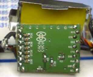
The Sipex SP3243ECA chip shown is described as
an
"RS-232 Converter" which would seem to indicate that the Axim does not
have complete RS-232 circuitry on the motherboard. While the text
describing the pads is hard to read (the cb on the right is just over
half
an inch high) the markings match the sequence in the table above.
Additionally, the top of the left image matches the right side of the
right
image.
The use of the above chip and circuitry appears to meet a
"standards"
rather than technical need. The RS-232 standard specifies 12volt
signals where the base PPC uses 5 volt circuitry, so the above
apparently
only boosts the 5v signals provided from the PPC to the standard 12v
signal
level.
Testing has confirmed that connecting serial
communications
directly to the PPC connector on the Axim and i700 will
provide
serial communications to and from most serial devices.
There are about 25 other descrete surface mount components, most of
which appear to be resistors or diodes and one transistor.
Almost immediately after this cable shipped,
it was discovered that devices using only the Tx/Rx/Gnd connections (no
hardware flow control) would not work with the Axim and this
cable.
It appears that the cable circuit is expecting voltage on the DTR line
to power up the cable.
This posting is preliminary, but I think cracked this problem with
no
electronics, just jumpering connector pins. Here is my
investigation
process;
I intitially confirmed a serial connect session between a Jornada
and
Axim using vxHPC, settings
4800,8,n,1
using a null modem connection... communication occurs in both
directions
with no issues.
Using a Magellan GPS (which has only tx/rx/gnd connections) I
confirmed
that the Jornada received the Magellan's serial NMEA output, but the
Axim
did not.
On a hunch, I inserted my RJ-11 serial
connector
schema between the Magellan and Axim and clear NMEA output
from
the Magellan appeared on the Axim's terminal screen... problem solved.
The db-9 pin jumpering can be seen in the wiring diagram for the
RJ-11
serial adapter diagram below (the db-9 pins 1, 6 and 8 are connected)
and
you can make your own decision as which connection did the trick.
The trick is to loop one of the the Axim's serial state pins signal
to power the GPS "DTR" pin and trick the Axim cable into powering up...
since you will need to deal with the null modem requirement for a GPS
connection,
the needed gender change, null modem and pin loop can be built into a
single
adapter or you can customize the GPS connector. Would suggest
against
jumpering the cable from the Axim as PC connection's flow control would
be impacted.
I would, however, suggest considering creating the two
headed serial cable using the same information that is posted above
for the Jornada serial cable. I cannot tell you how many times
this
cable has saved me time and trouble when serial connections to other
devices
were necessary.
RJ Serial
The serial connection system that I have been using for about 20 years
has proven to be a real asset in connecting a wide variety of devices
to
both the Jornada and the LX. The basis of this system are six conductor
RJ-11 "modular" telephone type cords which provide an "automatic" null
modem (or not) connection to a wide variety of serial connectors.
In the image below all of the connectors shown use telephone type
six
pin "RJ" connectors, wired in a way that provides significant
flexibility.
Most of the connectors below that were used with the LX are now serving
with the Jornada.

The LX serial connector is 10 pin, two rows of 5 pins.
The LX serial connector pins on the LX match "standard" PC serial DB9
connectors...
pins 1-9 will match the db-9's pins 1-9 and pin 10 is protective
ground... I _think_ pin one is the upper left when looking into the
connector with the LX bottom down. (shouldn't matter, if you wire
it exactly as a DB-9 and it doesn't work one way, invert the connector)
Note!!!--->>> While the LX connector "looks
like" the same spacing as a standard ide hard drive connector, it is NOT
...however, it is the same spacing as the small laptop ide
connectors, so, if you can obtain a laptop ide connector, it is
possible to cut off a ten pin "chunk" and fabricate a working connector.
The second part of the system are DB-9 (or 25) connectors with modular
RJ-11 (6 or 8 connector) DB shells. These can be found in most
electronic
shops, but are generally either wired pin to pin or with a pigtail that
goes only to a single pin that you decide in which pin position to plug
it into. The following requires a bit of cutting, stripping and
soldering.
I wire these as follows. NOTE! since I have found a great deal of
descrepancy
in how RJ connectors are numbered and colored so the following is a
"Back
side (wire lead side) view" of an RJ-11 jack.
While the colors accurately represent the traditional wire "pairs"
it
is extremely common for the sequence to be reversed, which is OK for
phone
connections, but not for serial connections.
  RJ-11 as viewed from
  the connection lead "Back (wire lead) Side"
  of an "DB-RJ shell" jack
         +----+
 white   | -- |
 black   | -- +-+
 red     | --   |
 green   | --   |
 yellow  | -- +-+
 blue    | -- |
         +----+

Then wire the connections to a DB-9 or other serial
connector as follows.

 db-9   RJ-11              DB-25
 -----  --------           -----
 1,6,8  black              5,6,8
 2      red                3
 3      green              2
 4      yellow             20
 5      white and blue     7
The six conductor telephone type cords should have six pin RJ-11
modular connectors attached so that the connections on each end are
"flipped"
after crimping. In the case of the LX connector, after soldering the
wires
to it, I crimped a modular "plug" on the other end of the wire to keep
size to a minimum.
"Flipping" means if you hold the ends side by side so you can see
the
wire colors through the clear plastic, the colors in the connectors
will
connect to the pins on each end in reverse order.
That's all there is to it. I orignally used a single 10 pin LX
serial
(shown in the picture) connector with a few inches of six conductor
telephone
cord ending in a 6 pin telephone type RJ-11 modular connector, but
after
the camera entered my life, I made a similar cord that included a 4"
cord
and 1/8" audio plug (from a dead stereo headset) in addition to the HP
serial connector and modular RJ-11 crimp. This allows me to start a
download
using Itoh's LXDC software and put the connected units into the belt
pouch.
Both the camera and computer automatically shut down after the
download.
As for the RJ-11 to DB9 adapter shown in the picture, I was able to
cut it's size in half by removing the metal shell from the DB9, then
cutting
the RJ-11 portion of the plastic shell off and gluing the essential
pieces
back together. A good molding company could probably cut that size in
half
again.
The "Carry Kit" shown above includes a 6pin modular coupler and a
six
foot section of six conductor telephone cord. The cord serves both as a
serial cord and as a modem telephone connector.
In addition to the DB-9 unit shown, I have an RJ to DB-25, an RJ to
Mac Mini Din plus mini DB-9 and DB-25 gender changers that gives me
full
null modem connection capability at a fraction of the size and weight
of
most cables.
I have also replaced the standard serial connectors on a variety of
serial devices such as the Tripmate, the X-10 CP290 and other serial
devices
with an RJ-11 modular crimp connector to provide a simple easy small
connection
to the LX. Not only the LX, but each of the desktop computers I sit at
has at least one RJ-11 cable on the desk next to the keyboard for a
variety
of uses including LX file transfers.
Coupla notes. The beige modular RJ "End to End" connectors must have
six pins and be wired so the pins on the same side of the connector are
connected to each other. That provides a continuity of the "null modem"
wiring if one or more cables are connected in series. I have
successfully
run serial with these connections in excess of 200' with no problems.
It
is also easy to customize connectors to directly connect printers and
modems
with the same modular cables.
In addition, I carry a short 1" section of "unflipped" telephone
cable
with modular connectors plus an additional"End to End" connector. When
this is included in any cable connection, it serves to effectively
remove
the "nul modem" effect of any cable/connector combination.
However, the above will system will work almost anywhere except
for an ActiveSync serial connection which apparently actively uses all
of the flow control signals to maximize serial throughput.
Finally, no picking nits about the RJ-"11" description. While I know
that there is a different number designation for each "RJ Modular"
connector
depending on the number of pins and other configuration issues, my
experience
has shown me that most of the world only responds to "RJ-11"
